|
| M. Garschhammer, R. Hauck, H.-G. Hegering, B. Kempter, I. Radisic, H. Roelle, H. Schmidt Munich Network Management Team University of Munich Oettingenstr. 67 D-80538 Munich, Germany {garschha|hauck|hegering|kempter|radisic|roelle|schmidt}@informatik.uni-muenchen.de |
Nowadays, IT infrastructures are vital for companies of all orders of magnitude and all industrial sectors. Simultaneously, users are demanding more features, more security and more reliability regarding the provided services. Therefore, a user- and quality-oriented management of the IT systems providing these services is required. Overall, this leads to a service-oriented view on IT infrastructure integrating the user's view as well as demands regarding quality of service.
The emerging universal service market has to face this trend. Hence, all players in this market are exposed to strong competition and are forced to think in terms of services, quality of service (QoS) parameters and service agreements when talking to their customers rather than discussing parameters of network devices or end systems. Increasingly, new requirements such as business process outsourcing and e-commerce extend the range of services from (classical) communication and Internet services to complex application and value added services.
In order to address some of the problems associated with service management, the Munich Network Management (MNM) Team has developed the MNM service model [2] that defines commonly needed service-related terms, concepts and structuring rules in a general and unambiguous way. Our service model is intended to help to analyze, identify and structure the necessary actors and the corresponding inter- and intra-organizational associations between these actors. Since it also covers the complete service life cycle, it helps to establish, enforce and optimize information flows between organizations and business units. By this means it supports service planing and provisioning by systematically structuring the specification of a service, enabling the consistent modeling of provider chains and deriving requirements concerning the service functionality. Service operation is optimized by the detailed model-based analysis of necessary activities including personal, resources and information flows as well as their implications on the quality of the service.
The MNM service model specifies basically a formal framework which helps creating a user- and quality-oriented model of a service. Although we also use well-known UML class diagrams to define parts of the MNM service model, we have to emphasize that the MNM service model is a conceptual meta model not leading immediately to an implementation. Up to now a guidance for applying the MNM service model especially in regard to gathering the necessary information, is missing. To support this difficult task, this paper presents a service modeling methodology for the MNM service model. The methodology is a result from experiences gained while using our service model in internal projects and in numerous industrial cooperations as presented in [3]. Overall, the presented methodology guides the modeler through several steps and decisions leading to several diagrams of different types modeling the considered service.
The remainder of this paper is organized as follows: Section 2 gives a brief overview of related work, especially in the field of software engineering, which we used as our main inspiration. Section 3 presents a brief introduction to the MNM service model as a basis of the service modeling methodology in section 4. This section also explains the applied concepts and defines the modeling process. Finally, section 5 concludes the paper and presents further work.
The Telecom Operations Map (TOM) [14] introduced by TeleManagement Forum focuses on the end-to-end automation of communications operations processes. The core of TOM is a process framework that postulates a set of business processes that are typically necessary for service providers to plan, deploy and operate their services. Hence, we use the specified processes in combination with OSI's system management functional areas [5] to structure and define management activities during service modeling.
Furthermore, we have also adopted the concept of a service life cycle as proposed in [4] in order to identify all possible interactions needed to accomplish a service. The identified interactions are then added to the service model during the modeling process.
Obviously, service modeling methodology is highly related to the area of software engineering. Although it is not our goal to define a process for implementing services, the basic techniques concerning notation and methodology are comparable. Therefore, we took a thorough look at existing software engineering processes. In particular, the Rational Unified Process (RUP) [8] was examined as well as a RUP-based process for specifying component-based software [1].
Cheesman and Daniels separate software development in two distinct processes: management process and development process [1]. While the management process schedules work, plans deliveries, allocates resources and monitors progress, the development process creates working software from requirements. Thus, each development process can be used with a variety of management processes (e.g., waterfall, iterative, evolutionary process). We adopted this distinction and concentrated on specifying a generic development process, thus allowing to use any existing management process.
From the RUP we took the means to represent the process, especially the notions of workflow and artifact. In RUP a workflow is defined as a sequence of activities that produces a result of observable value [8]. Artifacts are the deliverables that carry information between these workflows. As we are not concerned with service implementation, the workflows covered in this paper roughly correspond to the requirements, analysis and design workflows of the RUP.
Furthermore, we took into account the work done in the area of Open Distributed Processing (ODP) [6]. The major goal of ODP is to define a set of standards that allow the cooperation of any distributed system implemented using heterogeneous resources and by multiple organizational domains. For this purpose ODP specifies five viewpoints whereas every viewpoint is an abstraction of a distributed system concentrating on a particular set of concerns. However, ODP is not explicitly specifying a new modeling methodology. Instead, they are applying standard object oriented approaches [7] which are already considered by the analysis above.
Basically, the MNM service model consists of the basic service model, which contains the three most relevant roles, the service view, which focuses on the service part of the customer-provider-relationship and the realization view, which concentrates on details of the provider's service and management realization. All parts together form the MNM service model which is presented briefly in the following sections. A complete derivation and description of the service model can be found in [2].
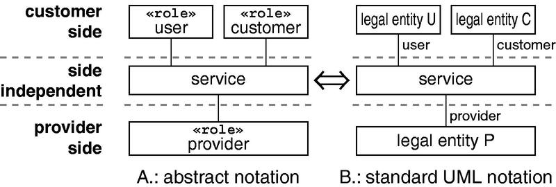
The basic service model shown in figure 1 is introduced in [3] and consists of three universal roles interacting with a service: user, customer and provider. Considering these roles and their associated domains, the basic model is divided into three parts: customer side, provider side and side independent part where the service is located.
In a standard Unified Modeling Language (UML) class diagram, to model these three roles and to express the fact that they are taken in by different players, three different classes have to be modeled. As all roles generally are carried out by legal entities, the corresponding classes have to be made distinguishable by auxiliary indices in addition to the class name ``legal entity''.
Instead of using standard role notation in the basic model, a new stereotype << role >> is introduced. The notion of this stereotype is to express that a certain legal entity takes in the specified role. Consequently, figure 1-A is equivalent to figure 1-B. As the notation using the stereotype role is much clearer for the basic model, figure 1-A is called the abstract notation of the basic service model. Figure 1-B outlines the notation to be used on instantiation of the model.
The understanding of a service must be the same for both customer side and provider side. We follow the concept of service orientation which postulates the realization independent description of the service from the perspective of the customer side. The side independent aspects can be found in figure 2 between the two domains symbolizing customer side and provider side.
Side Independent Aspects According to the main interaction classes identified in [2], the service consists of usage and management functionality. Both must satisfy a set of QoS parameters. These parameters define the minimum required service quality in order to be useful for the customer side. The QoS parameters are qualitative values. The usage functionality covers the interactions needed by the user. These interactions represent the actual purpose of the service. Besides these, interactions beyond the service's purpose are needed to fulfill the customer's duties, to customize the service according to user's needs and to control the provider's service provisioning. The management functionality comprises all these interactions. The service agreement substantiates the service by describing the usage and management functionality and setting bounds to QoS parameters.
The information presented up to this point describes the service demanded by the customer side and provided by the provider side. To actually be usable, a service interface must exist between these two sides. Service primitives, protocols and (where necessary) physical connectors are represented by these interfaces. In the same way the functionality was split up into usage and management functionality, the interface is split up into a usage interface, called Service Access Point (SAP), and a management interface, called Customer Service Management Access Point (CSM AP) [9], where the corresponding management functionality is accessible.
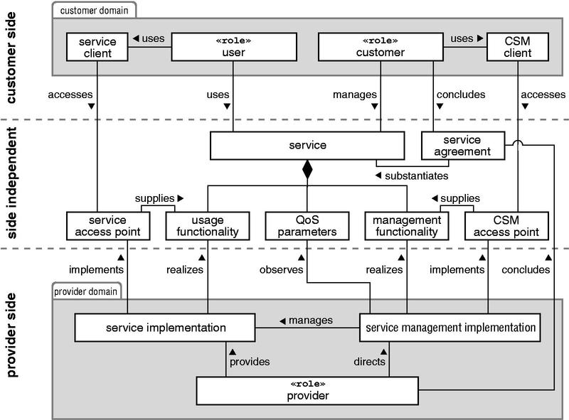
Customer Side In most cases some equipment is needed on the customer side to access the service functionality. The service client and the CSM client allow user and customer to access the functionality at the SAP and the CSM AP, respectively. These clients (e.g. telephones, computers or applications) must be compatible to the physical and logical aspects of the service interfaces. The sole responsibility for the clients rests on the customer side.
Provider Side The main task of the provider is to make the service available. This includes all aspects of the service, namely the usage and management functionality fulfilling the QoS parameters and the interfaces to enable the usage and management of the service. For this reason the provider needs a service implementation consisting of all knowledge, staff, software and hardware needed to realize the usage functionality and the SAP. The provider is also responsible for service management. In order to fulfill the primary goal to keep the service above the agreed quality level, he directs his service management by specifying e.g., a set of policies that are enforced by managing the service implementation. Of course, goals like high efficiency and low risk are also pursued. Furthermore, service management implements the management interface for the customer side (i.e., CSM AP) allowing controlled access to the management functionality.
Comparing both, the basic model and the service view, the provider's single association to the service in the former is split up into six subtler ones in the latter.
In contrast to the service view the realization view is used to model the provider-internal realization of a service. As many value added services are composed of sub-services that are supplied by various sub-providers, the realization view has to be capable to express exactly this situation.
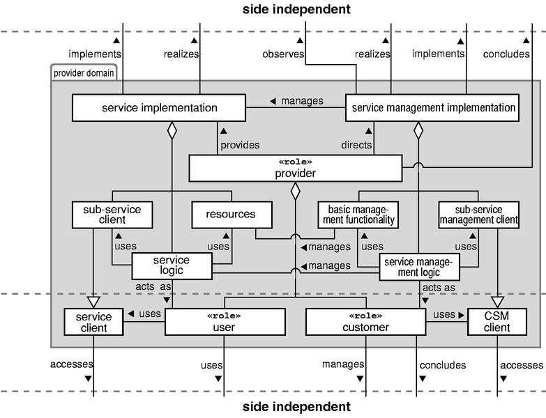
A provider contracting a service of another one acts as a customer to the latter. This means that the provider domain embeds the tasks of the user/customer role and the provider role simultaneously. As such, we can reuse the already modeled associations between customer and provider domain in order to model the associations regarding the relation of provider and sub-provider. By expanding the provider domain with the entities of the customer domain, we create an enhanced model of the provider domain.
Figure 3 illustrates the provider-internal realization of a service and its management. By means of integrating customer with provider side both roles of the customer side reside within the provider domain. Thus, the customer role and the user role are part of the provider role. The service client and the CSM client used to access the subsidiary interfaces must be part of service implementation and service management, respectively, to permit interactions with a sub-provider. As a consequence, there is a need of new elements within the service implementation and the service management.
The service implementation is composed of resources made available by the provider himself and sub-services that are accessible through sub-service clients. Hence, we introduce a service logic to control both, the usage of services as well as the usage of the provider's resources. Thus, our class diagram shows the class service implementation consisting of the classes sub-service client, service logic, and resources. The sub-service client is actually just a refinement of the generic client added to the provider domain.
The service management will use functionality of the traditional network, system and application management, the so called basic management functionality (BMF), along with the management functionality provided by subsidiary services. In consequence, there has to be a management logic controlling the BMF as well as the sub-service management client for the subsidiary service management. The management logic treats the service logic as a managed object. Corresponding to the service implementation, we model the class service management as an aggregation of the three classes BMF, service management logic, and sub-service management client.
As both logics use corresponding clients to access the sub-service and/or their management respectively, they act in the role user (service logic) and customer (management logic). We model this correlation with two associations. Overall, only five associations are needed to realize a connection between a provider and his sub-provider.
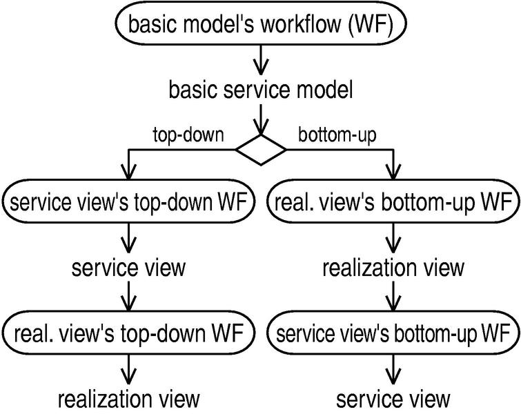
In this section we are presenting the modeling process for the MNM service model. A short overview explains the structure of this section depicted in figure 4. This process consists of three out of five workflows. Firstly, the basic model's workflow (see section 4.1) must be accomplished which delivers the instantiated basic service model. Afterwards, the decision follows whether a top-down or a bottom-up design should be undertaken, which depends on the motivation of the modeling project. Both the top-down and the bottom-up process generate a service and a realization view, but the creation of the respective models is done in reverse order. The top-down process, described in section 4.2, starts with the service view's top-down workflow (see section 4.2.1) delivering the service view. It is followed by the realization view's top-down workflow (see section 4.2.2) generating the realization view. In case of the bottom-up process described in section 4.3, firstly the realization view is generated by using the realization view's bottom-up workflow (see section 4.3.1) as in this case the most significant requirements are derived from the components implementing the service. It is followed by the service view's bottom-up workflow (see section 4.3.2) delivering the service view.
Each workflow consists of several activities. Each activity generates output artifacts on basis of input artifacts. These are visualized by unframed text in the process figures. Identified artifacts are used to specify a class of the MNM service model in regard to the analyzed service scenario. This means that, e.g. a UML activity diagram (as an artifact) specifies important aspects of the service functionality and the service management functionality.
When a workflow is finished, the appropriate class diagram of the basic service model, service view or realization view can be created, respectively. For this purpose, the classes of the meta models introduced in section 3 are instantiated by defining a meaningful name derived from the associated artifacts.
During our work we identified three different motivations for modeling a service. These modeling approaches vary in the intention the service model is used for. The modeling cases are as follows:
Reverse engineering Nowadays, many IT infrastructures providing services already exist but for which no formalized description is available as they grew over time. Often the involved parties demand a redesign of the service implementation to obtain a cheaper or faster realization e.g., by outsourcing parts of the implementation. Hence, the goal of this modeling case is to describe an existing service.
Bid invitation In case that a customer decides to obtain a service by applying the concept of outsourcing, the demanded service must be described properly in order to create a bid invitation for providers. Applying the service model reveals the advantage of a formalized service description, preventing the customer from forgetting important details or specifying ambiguous facts.
Offering The third case a service model is needed for, is the creation of an offer. If solely the requirements of the customer side have to be taken into account, the offered service can be created from scratch in a top-down manner. Otherwise, if service creation is restricted by an existing infrastructure, a bottom-up approach has to be applied.
The intention expressed by the modeling case influences the creation of the basic service model, the selection of activities as well as the direction of the modeling process and therefore has to be considered separately.
The process consists of three workflows - one for the basic service model, one for the service view and one for the realization view. Roughly two inverse variants exist for the service view's and realization view's workflows. The modeling case determines the variant to be selected. Each workflow consists of several activities requiring input artifacts and producing output artifacts. The next section explains these three workflows.
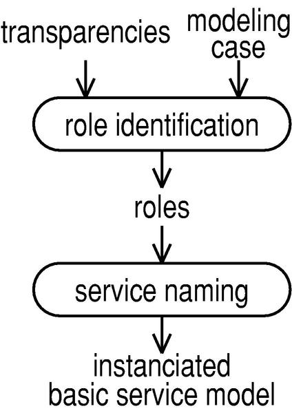
To create the basic service model, the roles and relevant services have to be identified. The first step is to investigate the relevant roles based on the modeling case and the transparency of the service hierarchy in respect to the customer side. It is followed by the derivation of sub-services. Finally these entities are combined to an instance of the basic service model. In the remainder of this section we are illustrating all modeling activities by using a figure that visualizes the input and output of all activities. The process for the basic service model is shown in figure 5. The workflow activities are depicted by boxes with rounded corners, while the artifacts are written in plain text. Input respectively output artifacts are associated to an activity by a directed graph.
Role Identification In the simplest case, there is a customer-provider-relationship covering just one single main service. The users are transparent to the provider, i.e. in this cases the provider does not know who actually uses the service. In consequence, the provider is not able to distinguish user and customer. Analogously, the sub-services the provider possibly needs in order to implement the main service are transparent to the customer, i.e. the customer is not aware of any sub-providers.
This simple case unfortunately does not model the real situation for all cases. E.g. the provider side must be aware of individual users if the customer demands service personalization according to user profiles or if user billing is required on behalf of the customer. Thus, the user is non-transparent to the provider side. Usually this case occurs, if the customer himself is also a provider who is just reselling a service to end-customers bundling their purchasing power.
Likewise, the sub-providers cannot always be transparent to the customer side. Particularly, if the customer side comes into contact with representatives of a sub-provider, for example while delivering parcels or repairing equipment installed on customer side.
Summarizing, a role can be transparent or non-transparent, which means that the role is either visible by the opposite side of the main service or not. The sub-service can also occur either transparent or non-transparent corresponding to the sub-provider of this service. Obviously, the roles customer and provider of the main service cannot be transparent.
The availability of this information depends on the modeling case. In case of reverse engineering the provider knows all relevant information. The transparency of users and sub-providers can be derived from the current service realization. In case of bid invitation just the main service is of interest and the customer knows if the provider must be able to address individual users. Thus, the only important transparency is known.
The last case, i.e. offering, can be mapped to one of the other two cases as follows: If a new service should be created from scratch the statements on bid invitation are valid. Non-transparent sub-providers cannot be identified at this stage of the modeling process. Their identification must be delayed until the realization is modeled. An offering developed on the basis of an existing infrastructure is equivalent to the reverse engineering case. Major parts of the realization are already known because the existing infrastructure should be reused.
Service Naming To specify the basic service model, the names for the main service as well as for all non-transparent sub-services must be defined.
A non-transparent sub-service is characterized by its provider being visible to the customer side of the main service. Consequently, a service name is needed for each visible sub-provider. Finally, the specified names are added to the basic service model.
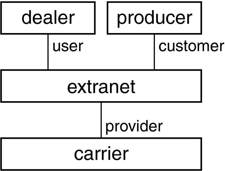
Figure 6 shows an instance of the basic service model for an extranet service bought by a producer of arbitrary products. The service is operated by the carrier. As the customer demands a charging of service usage, the users (i.e., dealers selling products to end-consumers) are non-transparent to the carrier.
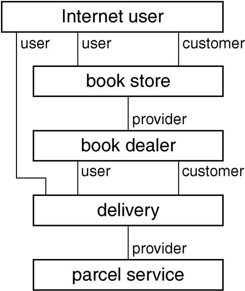
The basic service model in figure 7 illustrates a book store service. The book dealer offers any Internet user the ability to buy books in his store. As he is not able to deliver books all over the world by himself, he sub-contracts several delivery services provided by parcel services in the relevant countries. Because the terms and conditions of the various parcel services differ, the sub-provider cannot be transparent to the Internet user which is buying a book at the book store. The Internet user is the actual user of the delivery service because he benefits from the delivery of the book. The book dealer manages the delivery service but does not receive the book. Therefore, he is the customer of the delivery service.
The basic service model is the artifact which defines the relations between roles and services. This is always the starting point for creating the service and realization views. Referring to the modeling cases, one has to differentiate the top-down and bottom-up creation process: the identification of requirements vary in both cases. The top-down modeling process starts with customer requirements to define the service view followed by the realization view. Vice versa the bottom-up modeling process derives the realization view from service realization and defines afterwards the service view. In the remainder of this section the two modeling processes are explained. At the end of the section the modeling cases are assigned to the appropriate process fractions.
At first, the top-down modeling process defines the service view by analyzing requirements of the customer side. Afterwards, the realization view is derived on basis of the created service view. Overall, the top-down modeling process comprises the service view's top-down workflow followed by the realization view's top-down workflow, both described next.
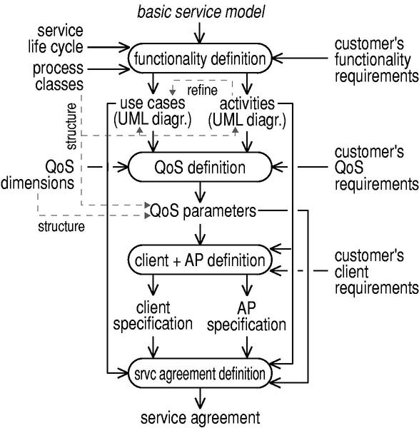
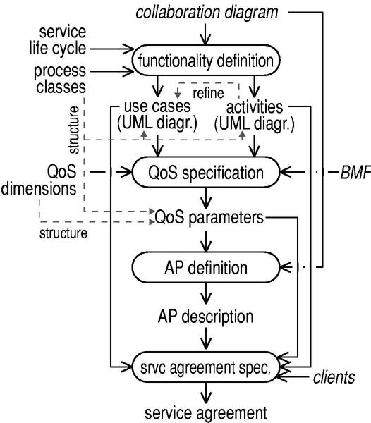
The service view's top-down workflow starts with the definition of the relevant usage and management functionality of the service followed by the specification of the QoS parameters for both types of functionality. In the next step, the client requirements of the customer and the access points are defined. Finally, one can derive the service agreement from the already defined model elements. The result of these steps is a complete service view. This workflow is depicted in figure 8. The diagram is complemented by additional associations showing relationships between artifacts which are represented by dashed arrows labeled with the type of the relation.
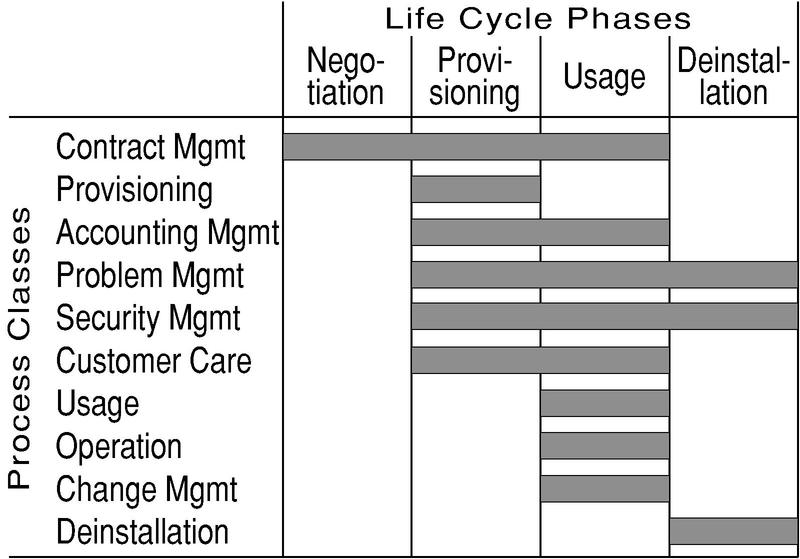
Functionality Definition The input for the definition of usage and management functionality comprises the functional requirements of the customer side, a process classification and the service life cycle phases. The process classification and the life cycle phases help to identify all required processes to accomplish a service. Additionally, both are also used for structuring reasons. The process classes used for the process classification and the service life cycle phases have already been specified in [2]. The process classes are derived from both the OSI systems management functional areas and the TeleManagement Forum's TOM [14]. The process classes and life cycle phases are combined as depicted in figure 9.
The output artifacts of this activity are a set of UML use case diagrams [11]. These diagrams show on the one hand the connections between identified processes and on the other hand, roles (actors) associated to processes which represent the functionality. A refinement of the three universal roles is possible in these diagrams by specializing each role.
Afterwards, each process of the functionality is specified by a UML activity diagram [10]. For this purpose, activities of each process must be identified and a process structure must be defined. Sequences, parallel paths and loops are supported. For dynamic control, conditions and signals can be used.
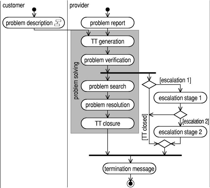
As an example an activity diagram of a simplified problem management process is shown in figure 10. It supports reporting of problems by customer or provider side. Domains and roles can be expressed by UML swim lanes. It defines the problem resolution as well as an escalation mechanism. The documentation of each problem is modeled by a trouble ticket system.
QoS Definition The second activity in the service view's top-down workflow is the QoS definition. To specify the QoS, the customer's QoS requirements as well as the activity diagrams from the previous step are taken as input. Especially the activity diagrams deliver useful indication for QoS definition: The begin and end of modeled service functionality activities resp. processes are very intuitive reference points for the specification of service-oriented and usage-related QoS parameters. In order to identify the relevant QoS parameters, QoS-relevant activities are combined to groups. In the problem management process in figure 10, the path from TT generation to TT closure obviously builds up such a group comprising the problem solving as a whole. Afterwards, these groups are analyzed according to the following QoS dimensions [13]:
A 100 percent availability of functionality is only ensured if all three dimensions comply with given bounds. Nevertheless, it is not necessary to define a QoS parameter for all dimensions for each identified group. Only characteristic QoS parameters should be included in the service view, gathered in tables or as textual descriptions, which are attached to the respective process. To reduce the number of QoS parameters, often several groups can be combined without loosing accuracy. We mark activity groups in the respective activity diagram by boxes in different colors labeled with a group name. E.g. duration is a characteristic parameter for the group problem solving.
Client and Access Point Definition The next step is to identify the requirements of the customer side regarding the access points of the service. These requirements can be derived from the infrastructure user and customer intend to use for accessing the service. If the service and CSM client are already in operative status, they can limit some properties of the access points. These limitations are an integral part of the access point requirements of the customer side. Other requirements can be derived from strategic decisions of the customer like scalability or reduction of heterogeneity.
The access point requirements as well as the functionality defined by the activity diagrams and the QoS parameters are the basis for the specification of the SAPs and the CSM APs. The output of this activity is a specification of the SAP and the CSM AP, which is attached to one or more processes as textual description, formal specifications or references to standards.
In the problem management process the service client is a telephone, a user needs to call a certain telephone number representing the SAP. The CSM AP is a web interface where the customer can access current information on the status of the problem solving by accessing the trouble ticket system. For this purpose a web browser serves as the CSM client.
Service Agreement Specification The so far defined aspects of the service can be combined in a service agreement. To obtain a definite service agreement, one refines the information in the service model by concrete bounds and values for variable parameters. In addition, legal aspects have to be taken into account [12], [13]. But the latter aspects are out of scope in this paper. Finishing this step, the service view is complete.
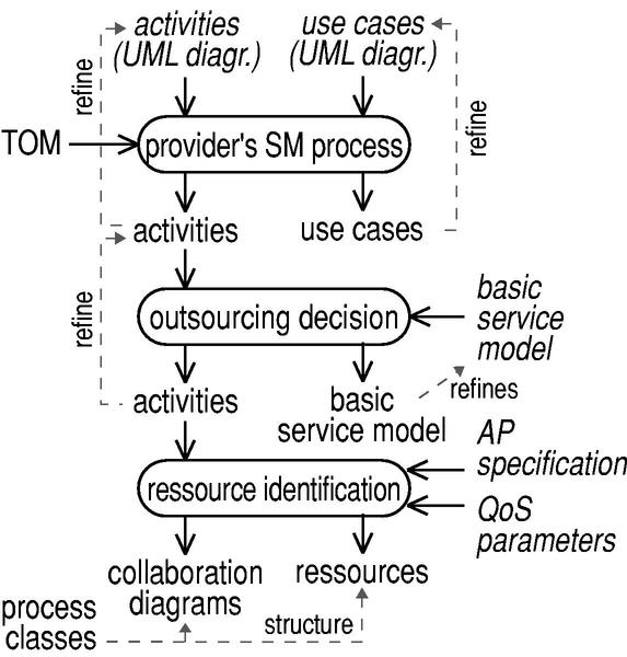
The realization view can be derived on basis of the artifacts created during the previously described service view's top-down workflow. The first step is to take the service functionality as a basis to define provider internal processes and activities. In most cases, the existing activity diagrams describing the service functionality are extended by adding these provider internal activities. Afterwards, the provider has to decide, whether parts of the service realization should be outsourced. Regarding the realization of the service implementation as well as the service management implementation, the required resources must be identified. Overall, the resulting workflow is shown in figure 11.
Service Management Processes of Provider Side Up to this point, only the management functionality for CSM [9] is modeled. Thus, only the requirements of the customer regarding the management functionality have been taken into account. Consequently, the functionality needed by the provider to manage the resources and internal processes still must be modeled. For this purpose the already in section 4.2.1 specified activity diagrams, representing the functionality required by the customer, are refined.
The TOM [14] defines a set of provider internal processes. Thus, TOM can serve as a source for defining the service management processes. For this purpose the provider can add new processes to the process classes defined in the previous section and extend existing ones by adding activities that are realizing the necessary management actions, like replacing stocks, internal report generation or quality assurance. Overall, the resulting refined activity diagrams represent the service logic and the service management logic, respectively.
Outsourcing Decision Afterwards, the activity diagrams are analyzed to decide which processes should be outsourced and which processes should be realized internally by the provider. This decision depends on various circumstances like the provider's core business, the existing infrastructure and various strategic considerations.
For each outsourced process the basic service model is extended by a new sub-service. For each sub-service one has to consider whether the user of the main service can be transparent to the sub-service and if user or customer comes into contact with the sub-provider. If there is no contact between the customer side and the sub-provider, the sub-service is transparent to the customer side and therefore marked with the stereotype << internal >> .
In the problem management example the 1st level support including the telephone system is outsourced to a call center. The CSM interface for the problem management process is realized by the provider himself. In figure 10 this outsourcing decision is modeled by a single composite activity, namely problem description.
For each sub-service one must define a sub-service client and a sub-service management client, which serve as the source for the requirement analysis in the recursive application of this modeling process on the sub-service.
Resource and Basic Management Functionality Identification For the activities which are provided internally, the provider must identify the needed resources. The previously defined activity diagrams guide this step. For each activity the needed manpower and devices must be identified as well as the access points of the processes. Furthermore, the interfaces must be mapped to resources. Afterwards, collaboration diagrams are used to model the resource interactions during the execution of the identified processes. These diagrams also integrate access points and sub-service clients. The collaboration diagrams represent the most detailed model of the service logic. They are the basis for optimizing the resource usage and the process implementations.
Analogously, the basic management functionality for the management processes must be identified. The relations of BMF, sub-service management clients and CSM APs are also visualized using collaboration diagrams, which represent the service management logic.
Finally, the QoS parameters defined in the service model must be mapped to values, which are observable by the BMF. Finishing this step leads to a finalized realization view. Overall, the realization view defines the service architecture supporting its realization as well as its further development.
The problem management process requires several hardware and software, namely for the trouble ticket system and the web server realizing the CSM AP. The management of these components is accomplished by traditional network and systems management.
In contrast to the top-down modeling process, the bottom-up modeling process starts defining first the realization view on basis of the provider's requirements. Accordingly, the existing infrastructure is analyzed in order to, e.g., reuse of existing components. Then, using the realization view as a basis, the service view is created by abstracting from irrelevant details. Thus, the bottom-up modeling process comprises the realization view's bottom-up workflow followed by the service view's bottom-up workflow.
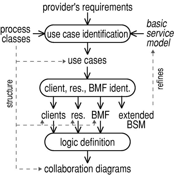
The realization view's bottom-up workflow starts with the use case identification followed by identifying the components that are realizing the service and finally by defining the service logic and service management logic. Figure 12 depicts this workflow.
Use Case Identification Firstly, the process classification defined in section 4.2.1 is used to identify use cases relevant for service realization. The result is a set of use case diagrams. These use cases also assure that all relevant realization elements are found. Commonly, use cases should be identified in cooperation with current users and customers. In case of newly designed services that use an existing infrastructure, a ``virtual'', potential customer-side can be used to define use cases.
Overall, the output of this step are UML use case diagrams structured by the process classes, which roughly model the service functionality.
Client, Resource and BMF Identification All resources and sub-service clients used in the realization must be identified. The previous defined use case diagrams guide this step so that all important systems or participants are considered. New sub-clients imply a new sub-service in the basic service model which is marked with the stereotype << internal >> if the sub-service should be transparent to the customer side.
Then, the BMF for clients and resources is identified. I.e. all network, systems and application management tools are registered including their purpose. All specifications of realization elements are structured by the process classes described in section 4.2.1.
Logic Definition The service logic as well as the service management logic are specified using UML collaboration diagrams by analyzing the previously identified BMF, resources and sub-service clients. Furthermore, the SAPs and CSM APs have to defined. For this purpose, the specific service implementation can be used. Finally, the access points are included in the collaboration diagram.
As there is one collaboration diagram for each use case, this step defines completely the service logic and service management logic on a very detailed level. Finishing this step, the realization view is complete.
The service model is created by abstracting from the service implementation and distilling its functionality. Afterwards, the service's QoS is derived from the realization and the access points, resp. Finally, it is possible to specify service agreements. The workflow is shown in figure 13.
Functionality Definition As said above, the service view is gained by abstracting from the realization details. For this purpose, the collaboration diagrams are transfered to UML activity diagrams. Therefore, activities carried out by the realization's elements have to be distilled.
Regarding the management functionality it is necessary to eliminate all internal activities and processes of the provider and should not be visible for the customer. The result is one activity diagram for each collaboration diagram, i.e. for each use case. These diagrams represent the usage and management functionality.
QoS Specification This step is used to define the service oriented QoS parameters based on the activity diagrams created in the previous step. Additionally, only parameters are taken into account which can be observed by the BMF.
The QoS parameters are defined in tables or as textual descriptions attached to the respective use case.
Access Point Definition SAPs and CSM APs can be copied from the collaboration diagrams of the service logic and the service management logic, respectively.
The result of this step is a set of access points as textual description, formal specification or references to standards.
Service Agreement Specification The final step is to integrate the aspects of the service defined so far into a service agreement. To obtain a definite service agreement, refining the information in the service model is necessary. The concrete bounds and values of parameters can be specified according to measurements of the service realization. For completeness, legal aspects have to be taken into account. After this step, the service view is completed.
The modeling of a specific service starts with the decision which modeling case applies. Then, the basic service model is defined. After that, one either follows the top-down process or the bottom-up process depending on the modeling case.
In case of a bid invitation the top-down process is used, but the modeling stops after the specification of the service agreement. The realization is modeled by the provider, e.g. when creating an offering. This can be done top-down continuing the top-down process to model the realization view. Otherwise, the offering can be designed bottom-up which requires to use the bottom-up modeling process. The use cases needed in the process are derived from the bid invitation.
In case of reverse engineering the bottom-up process is used. The use cases for guiding the process are gathered from the current users and the customer.
In each case the modeling leads to a service oriented model, which delivers a uniform view on the service for customer, users and the provider.
In this paper we presented a methodology for using the MNM service model. Thus, the experience of the MNM team in service modeling and especially in using the MNM service model gained in various industrial cooperations becomes open to the public. The proposed methodology covers all steps of service modeling from role identification and service naming based on transparencies up to building a comprehensive service view and a realization view respectively. Depending on the modeling case different variants of the methodology have been introduced thus covering a broad spectrum of scenarios.
By utilizing well-known techniques from the area of software engineering, the application of our methodology is straightforward. It leads in a structured and easy-to-use way to a comprehensive representation of a service, easily understandable to both, provider and customer.
Our current work focuses on verifying and improving our methodology and refining it for special use cases. Furthermore we are extending the MNM service model to cover context-aware services. This will provide a first step towards a means for interchangeability of context information between different provider domains.
Acknowledgment The authors wish to thank the members of the Munich Network Management (MNM) Team for helpful discussions and valuable comments on previous versions of this paper. The MNM Team directed by Prof. Dr. Heinz-Gerd Hegering is a group of researchers of the University of Munich, the Munich University of Technology, and the Leibniz Supercomputing Center of the Bavarian Academy of Sciences. Its web-server is located at http://wwwmnmteam.informatik.uni-muenchen.de .